A1 – Designing what – Or how to design.

The starting point for me personally has been the education for a master degree in Architecture.

I was supposed to become an architect, but I must admit that no one was able to describe Architecture to me in a way that I could appreciate, nor could I express my ideas. What I can appreciate though is aesthetics. Beauty. These words speak to me and do not need further explanation as such. What I need to explain to myself and to others, is why…. Why are things beautiful, aesthetically pleasing. What is it about the configuration of visual objects that we generally like as opposed to what we dislike?  And why do we need the ugly to be able to discern the beautiful ? Through an education of art and Architecture that has been influenced by both extremely liberal, and then the overly strict environments and views on art as such, I have indeed become fed up with the notion that there is something “mystical” or “magical” out there governing things, something that does not have to be explained. At the same time I believe in the following: As an artist; If it is aesthetically pleasing  it is worth pursuing. If it is worth pursuing it is possible to engineer. Leave some work for experts, and focus on being the creator. As you maybe can gather my past has left me rather ambiguous on these matters.

So instead I will here present certain known concepts of shape and form through mathematical principles, and how certain people have come to bind them to the practice of architecture, art and the notion of aesthetics. Mathematics, through geometry and its sub – concepts, and understanding of it is my prime interest both in art and Architecture now. My contribution through this blog comes in the form of the linkage of concepts, and as you will see, the construction of what I have come to believe to be my idea of the architecture that has been presented to me over the years.

I do not presume to revolutionize Architecture through this blog,  I only wish to show what I think computer software industry has made a lot of designers forget ,through the development of interfaces as simple representation of complicated technology. Because once you start to dive into the depths of computational technology you start realizing just how naive your ideas were. And therein lies true revelation.

Digital programming – Competence in a creative process, and why it is increasingly valuable in an ever more complex Architecture.

I will start by saying that instead of a theoretical dispute, I will soon move on to examples and finally my own project, to show what I feel is the inevitable evolution of the Architect. I think this will also emphasize a new meaning of the word Architectural Design, and thereby add something to a discussion about Architectural Design Paradigms.

It has become somewhat apparent to me through my years as Architecture/art student and creative individual what inspires my creations. Sadly, I have then also come to see my limitations. As I see it, I have certain abilities that enable me to imagine 3 – dimensional space from limited input. So form seems to be my thing. This complies fairly well with research on how the typical male human brain works.

The problem is that these abilities have potential that seems to only realize itself when ideas are organized, on multiple levels, and calculated, beyond what my poor brain is capable of. Often it is difficult to see where your limitations lie when working on a design. The possibilities and ideas seem as vague dreams, and they can disappear just as fast if you don’t catch their essence. I say this because these ideas come from an enormous universe of more or less equally valid solutions to a problem, a universe that is far to big for any human to systematically catalog, let alone control. THIS universe is one that I feel should be more accessible, through computing power that nearly all of us are in possession of. Your own dream catcher.. This is what computers should have been all along, isn’t it ?

It seems that this is not remotely the case. Most computer software for design do not span the chasms of different disciplines, and so you are stuck with a tool that does nothing for you but produce a replica of what you sketched out as an idea on paper or produce something that you do not comprehend or care about the extents of. Using the software in the manner that the industry forced upon us, does nothing but keep design paradigms at status quo, which means little real creativity in my book.  Also consider this: How are you supposed to creatively master a tool that you don’t really understand on a fundamental basis?

I have to admit that I lack perspective and control of big Architectural projects, and especially I struggle with the validation of the design process. Maybe it is this struggle that has forced me to try out the creative process on another level. By another level I mean to say putting the emphasis on another part of the design process, and also the problem of reorganizing the management of the process itself.

Example:

The mathematical calculator is  still being used as an independent tool for calculating numbers used in more or less isolated incidents. The relation between the calculation and the use of the calculation is apparent. All laptops in use today have a much larger capacity for calculation than the traditional calculator , but it depends largely on the software implemented on the computer. Given the right algorithms, one can perform a variety of tasks, across the borders of a single piece of software and on to the next. The problem with this capacity is that it requires a large amount of specialized skill and validation of that skill, and so calculations can not be directly used as validated design results.

When referring to design on another level earlier on , I am really talking about making a tool that can take decisions for me, scan the universe of possibilities, all according to  my  recipe, or algorithm. This would in my case be a digital tool that you produce yourself, for the task or tasks that you have set out to handle. This method of working is in Architectural design loosely called tooling, and commercially it has been exemplified in the book “Tooling : Pamphlet Architecture 27 ” by Aranda and Lasch. http://www.arandalasch.com/ or http://www.amazon.co.uk/Tooling-Pamphlet-Architecture-Benjamin-Christopher/dp/1568985479 The problem I have with this kind of approach in general though, is the “starting from scratch” – notion. I felt at least on my own behalf that I should make use of what has been there from the dawn of computers. The consequence of the inevitable fact that we will someday get replaced by artificial life.

A method for solving a problem can be called an algorithm.  We all use them, all the time. Some are rather simple, some are extremely complex. Algorithms are used in computer programming for solving specific problems, performing certain specific tasks. The computer does not know what it is doing( as of this write up anyway 🙂 ), nor does the end-user of a piece of software, and yet these calculations and their organization are what make it all happen.  By making software more flexible though, applications can now be extended fairly easily by the end-user. By writing the code for an extension, plug- in, script or routine, or just “plugging it in”,  it is possible to extend the capabilities of an application in the way that you see fit to solve a task. Industry standards can potentially be implemented through libraries and classes used in the different programming languages through API’s( Application programming interfaces), and thereby be directly be incorporated into the melting pot that is the software application.

So what is my reason for dwelling on this ?

I became acquainted with a flexible piece of software some years ago called Autodesk Maya. It is an application for representing  modeling and animation in 3D virtual space. The good thing about this piece of software is its core flexibility. If something in this software doesn’t fill your needs, you can change it or create the functionality yourself so that it does what you want.  The reason for this flexibility is that the program consist of so called ‘nodes’, that perform certain tasks and connect to other nodes( Like a black box concept). You do not need to know what is going on in a node on all levels of application design, but if you do you can control just about everything that goes on in this piece of software. Why again is this interesting ? When I started thinking about making my own tool, intuitively this is what I was interested in. Mathematical building blocks. Modules that can be reused and repurposed. From working with traditional GUI(Graphical User Interface) of an application, where you move, drag and click, there is quite the adjustment when you contemplate using a software in a manner like this. But If you are interested in being creative with software tools, either in author – time or during run- time, I would say this is the only way to go.  I think this is by far the most interesting path for the Architectural designer to take in using this kind of Computer Aided Design software, although the graphical windows of the application interface would have you think otherwise. But aside from generating objects inside the software through a setup of rules and regulations( a system) , I do not see creativity in neither this kind of software or the Computer – Aided Architectural Design software like Autocad, Revit or Archicad.

Autodesk Maya has its own scripting language,MEL(Maya embedded language), which directly interprets commands made by the user onto the ‘physical’ environment in the graphical user interface. This is like rapid prototyping , where the effects of your literary commands show up immediately in the environment. This language operates on one level, while the programming language of C++ operates on a lower level(Lower meaning more abstract). I have chosen to set up a  diagram of the different levels here for those who need to visualize it:

Level 3 – Maya visual
interface( Interactive on the level of Microsoft Windows) This is
where the designer tends to do most of his/her work.

Level 2 – MEL (Maya
Embedded Language) Scripting language operating directly on objects
in the Maya environment.

Level 1 – C++ / Maya API
Programming language. The code in which the application was written.
This is general language that has to be compiled into a program and
then run by the user.

Level 0 – Binary
language. Really only two digits combined in ways to make other
symbols.

This diagram can be disputed pertaining my choice of Level – digits, but for now I will let them stand. I will not delve on assembly language here.

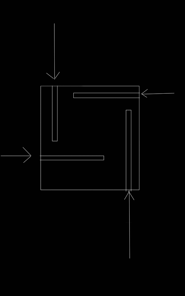
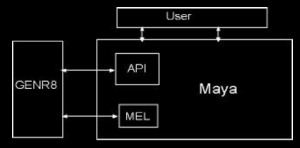
For a given plug- in (extension of  maya’s functionality),  you could set up a diagram like this( showing relation) :

relational-diagram-genr8

So initially I have been talking about design on a different level, and here you have my take on it:

Instead of designing on level 3 , it is desirable to start designing a tool on  level 1. By way of this abstraction level I will then be doing genetic operations in binary material.

A2 – My starting point.

In the first theoretical part of my blog I talked about How I see myself in the process of Design. Now I would like to get started on how I would go about my process, changing the original Genr8 plugin.

First of all, as I started to gain interest in the topic of artificial life, and started to conceive a project of my own, I soon realized how different this was from anything I had ever done before. You see, the creative process in Architectural design as an art is surrounded by myth, but in truth is a very simple(but painful) process. People like to think that the best ideas ever conceived have come in the form of sketches on napkins while sipping to red vine in some exotic location.  It is just not the truth.  This way of regarding the artist or the process will get you nowhere intellectually.

Parametric Design software  has been conceived as  a method of correlating dimensions and variables with geometry where as when the fundamental part- values change, whole segments change as well. Using this with CAD – Software it is supposed that you get a degree of creativity in the process because you would actually see the result of your actions immediately. (Like a paralell to scripting)

Well, as I talked about in my first post(A1), you are still working with the notion that your ONE hand so to speak, is creating the masterpiece, because so many considerations have to be taken into account for EVERY LINE THAT YOU DRAW in your models.

So my idea has been to introduce stochastic principles, probability and evolution into the mix.

There is no magic, there is no reinventing the wheel. I am simply  asking ; why not try to design a system that can produce millions of designs where all those considerations(read: parameters) are taken into account – All the considerations that you cannot keep in mind when designing by “hand” ? Why not try, instead of fighting the current ?

Basically I start with the pieces of software that I introduced  earlier, namely Autodesk Maya and the Genr8 plugin.  The Genr8 plugin which is a plug-in application, an extension of Autodesk Maya 3D – software, is described in its entirety on the website linked above.  The literary references and background info take up volumes and will be described on the mentioned website, not here. To me, Maya and Genr8 are both amazing pieces of software, and most of all, they are extendable and can be manipulated.  From the designer point of view, the Genr8 Plugin is a mammoth of a plugin, with thousands of lines of code.  If you get past this early notion though, it is merely a mental obstacle to get your head around.  For me  it seems like investing in the first creation of Gottlieb Daimler as far as future design is concerned. What the plugin basically does is generate surfaces based on iterative rules and surrounding forces. Sound familiar ? Yes, the idea came from biology, and plant growth to be exact. A biologist named Aristid Lindenmayer described a system for animating the development of bacteria, which was then brought on to plants and ended up as L – Systems after the creator. It was found that nature’s processes in this regard were quite well described by the systems, and again this spawned ideas in creative minds. One of those ideas were formulated very precisely by Martin Hemberg of the Emergent Design Group at M.I.T. It created the Genr8 plug-in for Autodesk Maya, and through a C++ programmed application incorporated into Maya it seeks to generate, rather than manually describe, a design of a surface through evolution. This is my basic starting point.

What I have  done so far is to assemble and compile a debug version of the 2001 Genr8 plugin for newer versions of Autodesk Maya. Post B2 will show how I have gone about it, and also how I have started to analyze the Source code for the plugin.  Why ? Because if you learn which code/literary strings trigger which validated processes, you could be in possession of a very powerful tool for further development here. From the authors source code I have generated diagrams in Microsoft Visual studio C++ programming environment, through UML diagrams. These diagrams show how the code works and connects and they are essential to be able to decipher the original programming code. The UML modelling I have done up to this point of writing is very basic and based on dependency, heritage and composition.

So the purpose of my first two posts has been to introduce the idea of visual design on another level than what we are used to as Architects. But there is a giant leap from this idea to the generation of a validated situation(loci) with construction models.

Here I will start with the technical part of the plugin:

To examine the existing relationships and patterns in the computer source code, you can generate dependency graphs. In mathematics, computer science and digital electronics, a dependency graph is a directed graph representing dependencies of several objects towards each other. It is possible to derive an evaluation order or the absence of an evaluation order that respects the given dependencies from the dependency graph. If the derivation of something is possible, is dependent on dependencies of other elements, and the order of them. If there is no starting point, and every element depends on another, we have an impossible evaluation, and so a circular dependency. A dependency graph without such is called a directed acyclic graph.(exemplified in post B3). This is something good which we can work with and which we touch upon again when dealing with the inner workings of Autodesk Maya.
To communicate intentions of software, create layer diagrams(In Visual Studio, you can use a layer diagram to visualize the logical architecture of your system). A layer diagram organizes the physical artifacts in your system into logical, abstract groups called layers. These layers help you identify, describe, and differentiate the kinds of tasks that those artifacts perform. Each layer can also contain additional layers, or sub-layers, that describe smaller specific tasks that discrete groups of artifacts perform. One can then use these diagrams to keep e.g your own code consistent with the code of the original design.
To understand how the code implements a method, generate sequence diagrams.
To explore the structure of existing classes, create class diagrams.
To model and communicate different aspects of the system, draw Unified Modeling Language (UML) diagrams. These tools create a common glossary of sorts, for visualizing and discussing the inner workings of the software.

Software code(like Architectural design project structure) is getting increasingly difficult to manage, because of sheer size and complexity. Also, it is a proven fact that most people need to be able to visualize their ideas through some sort of figurative representation to be able to understand and develop. For explanatory and rhetorical  reasons throughout, substituting parts of that rhetoric for simple figures can and will help you in a design process. This is true also when it comes to programming.

So what is important for me when trying to understand the source code through uml diagrams ? For a start I would like to be able to have a diagram that shows me either class – or header files, and then be able to directly inspect these files to see their particular code. In this way I can appreciate what each function, object, sentence or word inflicts on other files, functions, objects, sentences or words. It is obvious that when 1 letter can bring down your whole application, it is necessary to have a control system for it. So while showcasing diagrams as fixed images can help people understand certain principles, it is nowhere near good enough to really analyze the calculations that are being done.
Another important part is the piece by piece method, where you seek to understand each function, all its methods and all its objects. This I am making good use of through extended unit testing. This approach though has to be supplemented, because if you contemplate that “the whole is more than the sum of its parts”, you also understand that pure technical knowledge will not automatically  give you a perspective on the design that is finally going to be made, nor the machine that will create it. But I can’t stop there. As mentioned sequence diagrams show what happens when functions are called and which files are involved. This is crucial for being able to visualize for others and yourself the broad strokes of the system, on a canvas that sometimes can seem without boundaries.

So, from there let’s start to generate some visuals. From compiling the code( Blog post B2), you get the compiled dll(Dynamic linked library), or mll as Maya calls it. From this, and with the help of Visual Studio, you can directly from the “Architecture” menu generate some diagrams. I have chosen to create a class – diagram + a dependency graph diagram with the “include file” – option. These can be seen also in blog post B2. The good thing about working with these in Visual studio, is:

In the case of the class – diagram: You can see the hierarchy of the plug – in by way of classes. Also you can when you want jump directly to the code to have a look. Bare in mind that for now I am just using these diagrams to appreciate the code and how it works.
In the case of the Dependency Graph Diagram: Here you can appreciate which files are included in the plugin( Directly or indirectly), which FILES are connected + externals from C++ standard libraries, Maya libraries and externals from windows sdk. Here also you can directly inspect all code by interacting with the diagrams.

For you to be able to generate the diagrams the compile must be completed without errors. Warnings are common, but most diagrams will not build with errors. Refer to blog – post B2 to get an idea of how to do it correctly.

It is said that the virtual function is the “lens” with which you can start analyzing a project. If we start from there we can see that we now have a possibility of much easier tracking code through the project, by just looking at the generated diagrams. If we start to look we can easily determine parent classes and child classes.
That beginning signals the end of this post, with the parts of the software being exposed as I move along…

A3 – Exploding a system

As blogs go, for me personally this is just as much learning as it is telling about it. In Architectural design you have something called exploded diagrams – drawings or models that show all the “parts” – exploded out in a straight- lined  direction according to object- shape, so that you can potentially see the relations of a structure.

First of all I have to say: It seems incredible to me that when dealing with structural notations or formulae, that most people don’t stop and ask questions. Of course on a personal level I do understand because it is frustrating and tough to have to consider and in fact appreciate the logic that propagates through systems described by mathematics. Nevertheless there are obvious underlying problems when doing geometric modelling  virtually or tactile without understanding the logic and interdependence of underlying variables and functionality.

That being said this blog post will only serve as a simple prelude to the complementing “technical” blog post B3. I plan to expose the elements of L-Systems through dissecting the Genr8 Plugin, and I am starting with the elementary math, as I truly do not believe one can be creative with interactive computer modelling systems otherwise.

A4 – Architectural Design Project.

Skyscrapers, or high rise buildings are basically very complex structures. The level of engineering and the size of these projects in real life make them mammoth tasks for even large international firms of architecture , engineering and entrepreneurship, no matter how big they are or how efficiently they may be organized.

I am not going to focus on all these details. I see a point in drawing parallels between the high- rise and geometrically visualizing a plant in nature. Especially I am interested in the way the plant conforms to its surroundings, and particularly how it originates and evolves by way of light from the sun through direct light, reflection and refraction. ( More on this can be found in blog-post B4)

Therefore my Architectural design will showcase some of the technical aspects of such a hybrid, such as spatial and structural organization of the architecton that I conveniently call the simplified skyscraper. Conditions being parameters of light angles, physical elevation, gravity and the context of the building. As stated in chapter 1.2 of the original Genr8 whitepaper ; ” One purpose of this thesis is to create a tool that is useful to a designer. It is certainly beyond the scope of this thesis to create a tool that takes all aspects of architectural design in consideration. The focus of GENR8 is on growth, and in particular we want to mimic biological growth. Architects are intrigued by natural form and they find  organic qualities in design very compelling. Furthermore, the architects desire a growth process that takes place in a specifi c environment and reacts to the elements of the environment. To narrow it down even further, we decided to create a tool that generates surfaces. Surfaces are obviously very useful to a designer and they can be used in a wide range of contexts”

It seems fair to take this simplified approach for a masters degree, as it takes engineering firms years to figure out the statics and technical details of a complex structural project + similarly long time for designers to conform to the implementation. As such it is futile to try to do the work of all these people. The properties of newer materials have also paved the way for an easier conceptual design route , meaning it should be possible to envisage a construction without having to solve for every constructional detail, as materials can be used to implement a lot of different constructional concepts. That is of course true for each generation, as  we conform to using what has worked for earlier generations without having to reinvent the wheel. That also becomes less interesting as the task is not so much that of making the building feasible constructively anymore, it is about functionality and the user-aspect. Additionally I am developing a concept of a structure, not from any pure imagination but from work done in computer programming, mathematics(Geometry), physics(optics), botany, language theory plus of course Architectural design.

Now before I move on I have to say that Architecture, and its industry has had a relatively limited scientific investigation of the topic of light compared to other scientific fields. Admittedly the masters of old designed great projects for harnessing the power and beauty of the sun, but compared to exact science in general, and especially technological advances, there seems to be a lot left to discover.

Light structure

Some years ago I did a limited and very simple project on a type of inverted architectural structure. It was inverted in the sense that the notion of maximizing the openings in the facade for the purpose of letting in as much light as possible, was now in fact inverted so that the structure facade had a minimal percentage of openings. The clue here being of course that inside, this structure had glass walls and floors where ever possible, letting light trough the facade by the short- end side of the glass rather like the principle of fiber optics. Here I refer to Huygens’s Principle. While light scatters circularly from an impact point between to mediums somewhat, it tends to follow a medium ,like glass, in a wave – like fashion, meaning it will pass through using the shortest way possible. Very interesting in this aspect becomes the concept of fiber-optics. Such concepts are in fact used not only for sending light but indeed also information. This of course opens up new possibilities in the functionality of a building.

Because of the limited time for the before mentioned project the structure had its origin in a simple plan drawing which was made for the purpose of showcasing the effect of the light as it was carried through the glass and projected onto an opposing surface.

 A4Dia

In an urban setting with a very warm climate there would be an abundance of situations where large scale buildings like high – rises would benefit from having controlled lighting and therefore a kind of inverted facade. Of course the lighting of buildings in general is made beneficial nowadays through blenders and light control systems. But this is far from the purity of a Corbusier church, where the light is “molded” into the church room. There hasn’t really been focus on light in the same sense in post modern architecture. I believe the reason for this is the focus on construction technology and the advances in construction processes.

The big issue with thinking in lines like these , on a big scale would be the sheer complexity of the construction. That is why I started thinking about a automation process. I have through my earlier blog posts begun an investigation of a plug-in for Autodesk Maya called Genr8, and by now it should be obvious what it is and at least to some extent what it entails. One should also now begin to see the connection between this automated growth process that is Genr8 and the diversity that lies in the application of a system like that, onto an articulated axiom, like for example a plan drawing and further more on to something like a structure of a building. In the very nature of L – systems as used in the Genr8 plugin is this : self -avoiding, space filling, self- similar curves that make up surfaces. While these terms are not regularly used in Architectural design, that is not because they are not interesting in that context. Rather we are not used to describing our graphical notation in the same terms. But in fact Fractals as described as a mathematical description of a naturally occurring phenomenon describe very well  the self-avoiding, space- filling and self- similar qualities that we appreciate in our Architectural drawings. Is that coincidental ?

So where do we start ? Well, considering the wide range of research being included through my literature list, I am now narrowing down to the city square block and the Architectural floor plan. I have started developing a partially user-defined system in that regard, where a visitor to my linked website could also visit the Skyscraper project page, choose a destination for the potential project, set the boundaries for it, choose environmental conditions and the values for their variables, settle on a base for the structure – and then set it off with the push of a button.

Somehow I would like to be able to develop a floor plan that would be capable of growing extensively upwards, keeping and further developing solutions to spacial problems or challenges. Is it possible ? Of course. Look at scripts you run through user interfaces of ex. Autocad/revit/Archicad etc. It is difficult however to be aware of what you are producing, and if what you produce serves the original purpose. For this I have settled on a technique which we often use in Architectural design which is sketch modeling. Using your hands and your thoughts to quickly produce a lot of different limited spacial models and molding your idea. What I want to do here though, is a bit different. While it is normal for limited models to come together into a coherent project, that simplified end product is not the ultimate goal in my case. Like reverse engineering I want to find the mechanisms that connect each spacial element, so that generic rules can be established and applied to other floor plans. The challenge would be many– fold:

  • Get an idea of a good floor plan for a tall building combined with the idea of my principle of organization and sunlight. A  generalization or  an average is a possibility, at least as a plan-drawing fitness tool.

  • Make the Genr8 plugin by Martin Hemberg work with plan drawings in the form of extended polygons or polylines.

  • Rework the plug-in accordingly. It seems to be possible to make grammars describe objects(genomes/axioms) more extensive than the simple polygon. The challenge there is to find these grammars.

  • Decoupling the growth process from the grammars. Make sure the grammars are not able to produce erroneous results(f.ex self – avoiding curve crashing with itself), and thereby being able to freely search an enormous amount of solutions. In this way the architectural process could then also return to “normal”, as you would be able to sit down and go through the chosen design, working out detailed solutions using more or less intuitive fitness assessment. Some research has been done in that particular respect ( See blog- post B4 on the topic of Rosenman, Schnier, Gero)

Now I’ve got an idea for how to attack this as an architectural design project. Using the thought of inheritance and composition in the c++ programming language which I have become accustomed to, I have also become a believer of the language’s UML idea of “Casting the solution in the same terms as the problem” as it is phrased in “Thinking in c++” ( Eckel, Bruce – Mindview, inc. , 2000)

Quote;
“tremendously beneficial because you don’t need a lot of intermediate models to get from a description of the problem to a description of the solution. ”

This in fact suggests to me that you have a balance which lets you more easily “sketch” out possible solutions while making sure they are valid for the actual problem. To me this is the “magic” that languages bring us, without getting to poetic : To be able to put into words what is too infinite to describe elsewhere. Being able to describe something in language or diagrammatically without worrying about it being interpreted as THE design itself is something architects and critics of architectural design struggle a lot with on a daily basis, and it is something of which you don’t learn in school.( The same can be said for most parts of this project of course).

Now begins a period of really pushing the limits of my intellect – very difficult analysis, implementation, testing and creative work in parallel that I have chosen to describe as :

Controlled desperation.

So with that I present a diagram of my Architectural project:


ProjectInANutShell