L-systems are the basis for generation in these studies of alternative methods for Architectural creativity. They are made up of many processes and procedures and in this case they mimic the growth of plants .
For the development of structures from axioms, which are the hypothetical “seed of the plant” we rely on abstracted processes. One abstraction used for interpreting code into virtual structure has been named a “turtle”. Imagine as an example such a being moving freely in no-gravity virtual space , and making graphical notation of the path that it walks. The turtle both rotates to obtain a new direction and moves forwards( or backwards, left or right), but for now I will focus on the rotation, since it can be discussed somewhat free of L-Systems in general.
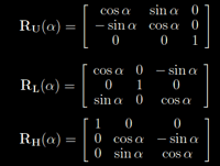
The rotation matrices for the rotation of the 3D turtle come in a form like this:

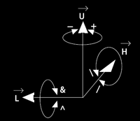
Here the angle is parameter and the RU is the TURN LEFT or TURN RIGHT of the turtle(LEFT=+, RIGHT = -). Also, there are symbols used for pitch, roll and turn-around: The RL is the PITCH of the turtle( & = pitch down , ^ = pitch up). The RH is the ROLL of the turtle(\ = roll left, /= roll right) and The TURN – around turtle( | = Turn-around(RU(180))).

The symbols inside the matrices are not to be confused with the symbols for the turtle movement. The
“-” inside the matrix means “minus”, while the turtle – symbol “-” means TURN RIGHT.
The way they work is that , for RU, the theoretical “x” axis remains as zero value, while left and right are calculated as values of cos(angle) and sin(angle) .
For RL, the pitch is calculated nearly the same, if you consider the UP and DOWN simply as another version of LEFT and RIGHT.
For RH, the calculation can be thought of as pitching the turtle 90 degrees, and then applying the RU matrix, just done all in the RH – matrix.

Of course this is just one set of notations out of many possible.
Going further into the math of the matrices:
The above mentioned matrices calculate states of a turtle, and this turtle in turn makes moves of a certain set distance . But how are the matrices calculated ?Well, first of all in computer Graphics we are dealing with the viewpoint in addition to the three dimensions, so what are we doing when we are playing with 3D software on the screen? Without giving it much thought we are actually constantly producing calculations of lengths and angles using trigonometry.

Consider rotating a 2D point (x,y) around the origin of a coordinate system by 90 degrees:
You would be given a matrix such as the one above. The new point (x’,y’) would be calculated by a matrix following the logic below.

or with circle trigonometry:

What you are seeing here is like saying :
- Take the ratio between the opposite side and the hypotenuse in a hypothetical “right triangle” according to your coordinate system and multiply it by the original x coordinate.(Call this SumA) Then take the negative value of the ratio between opposite side and hypotenuse and multiply it by the y coordinate(Call this SumB). The last value in the row is a zero so you basically calculate 0x1 here. (Following matrix calculation rules).
- Lastly add SumA+SumB to get the new x – coordinate, x’.
- Do the same with the last two rows, keeping in mind what it is you are actually doing.( How you actually are finding the new coordinates).
When you are finished you should be left with the new point (x’,y’) rotated 90 degrees counter-clockwise about the origin.

To rotate a point around another point , you could use the matrix beneath. Of course in 3D we rotate about an axis.

This is then extended to 3 dimensions by adding another row and another column, like you see here where the rotation is around the x- axis:

Going back to the top of the post, what you are seeing are the matrices that calculate rotation for the three different axis x,y,z.
• roll being the angle of rotation about the z -axis
• pitchis the angle of rotation about the x -axis
• yaw is the angle of rotation about the y-axis.
All these can be combined into one matrix, together with a translate matrix(Move etc..) to make operations more effective. But first a note about axis terms. Remember that there will be difficulties if you mix right-handed and left-handed systems or which axis is up , when you program for a API. In Autodesk Maya, the default up – axis is ‘y’ and the coordinate system is right- handed by default.
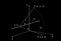
So consider now translating and rotating a point into a new point:


What you see here is a rotation about an axis parallel with the z- axis.
What we will continue to explore is the way in which this relates to L-System notation. The reason I find it extremely important to describe this process in full is twofold.
- We are used to describing creative work as if it came from out of the blue. This is a myth and a hindrance for most people, because when you get stuck at some point in the creative process it makes it almost impossible to get back on track. I want to make a comprehensive record of both the creative process and the “magic” behind it.
- In order to fully appreciate the designs that will be described in upcoming blog posts, it is important to explain the paths that lead there and the nuances that can make all the difference in a generative system.
The ways in which these matrices work may not be so obvious at first but they are extremely important, also when considering a creative perspective as an architectural designer.
Here I have just explained how a “turtle” in Turtle Graphics calculates how to rotate , through matrices. But the turtle also moves according to strings of letters in words – As in components of an L-system. This will be the subject of the next blog. The reason I start with matrices is that they are the technical foundation upon which you construct objects in a software like Autodesk Maya. Without knowledge of them you are simply lost..
Last time(Blog b2) I generated some diagrams of the software that is Genr8. Now It is time for some scrutiny of the elements of L-Systems and how they fit into that software
Keeping to the ‘A’ and ‘B’ parts of my blog I will here locate the files containing declarations and definitions of matrices in the Genr8 plugin, and later on I will find how it fits in the assembly of a generated object in Autodesk Maya.
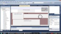
First of all I need to find the files that are relevant for obtaining the necessary info on its dependencies, its inheritance, etc… In other words I have to start using the Diagrams that I generated for the last blogs(A2,B2).
In the case of the Genr8 plugin we are looking at Euler – rotations, which are rotations about the x,y and z axes that we are used to.
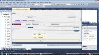
In the general project outline below ( Dependency diagram) you can see the mtransformationmatrix.h file encircled:

The next image shows files that are directly dependent on it, and the files which it is dependent on.

The purple nodes represent header files for Mvector and Mglobal, and they both include the MtransformationMatrix.h. Looking at the blue nodes, they represent Mstatus and Mtypes. A lot of these files are co – dependent, that is they include each other.
Now that we know what files are working together in this direct – relationship dependency, we can have a look at the code. Working with Visual studio this is never further than a click away.
Due to copyright laws this article can not reproduce the source code for the files. You can find them in the autodesk/maya/Include -folder.
MStatus:
The class takes care of error handling in the API.
MTypes:
File concerns version of Maya and consequently the version of plugin
MVector:
Provides access to Maya’s internal vector math library allowing vectors to be handled easily, and in a way compatible with internal Maya data structures.
MGlobal:
Provides methods for selection, 3D-views, time, model manipulation and MEL commands.
MGlobal is a static class which provides access to Maya’s model (3d graphical database). MGlobal provides methods for selection, 3d-views, setting the global time, adding to the DAG, and executing MEL commands from within the API. There are multiple methods provided in this class for executing MEL within the API. Plug-ins requiring the execution of MEL from the non-main Maya thread must use the executeCommandOnIdle() method to avoid program errors. MGlobal also provides methods for controlling error logging in the API.
MtransformationMatrix:(Linked PDF)
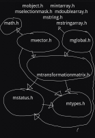
Now that we have a description of the headers, it is a good idea to look at the relationship between them.Making a diagram of the direct include dependency of these header files can look like this:

The arrows show which files depend on others directly.
Like I have described in the A3 blog post I will go on to look at the Lsystem, with its effect on the turtle and consequently generation of objects, but first cross- language issues have to be dealt with and understood.
Looking at our dependency diagram again; We can see that choosing incoming nodes shows us a first glimpse of the files dependent on our matrix – operations.
From the project files these are:
PolygonSurface.cpp, NurbsSurface.cpp,cmd.cpp, MelUtilities.h and Scaffold.cpp.
From the C/C++ Standard Library;
math.h
From the maya/include – library;
Mobject, Mstring, MvectorArray, MfnMesh, Mpoint, MfnNurbsSurface, MintArray, Mselectionmask and MstringArray.

Files are often interdependent of course but what we are looking for here is the usage of the transformation/translation matrices.
The interesting files are first of all the program – defined source files. It seems though that to appreciate the complexity of this code we will have to find a way to graph the calling of functions. That entails debbugging with tracing of function calls. The ways in which this could be done are quite a few, but I have already touched upon how I plan to do it. In addition I will show in detail how that is done.
So I am pondering on how to understand how the Genr8 plug-in works. But parallel to this I have to be able to work with the plug-in in the environment it was meant for, namely Autodesk Maya. Therefore, it is time to investigate what this piece of software actually does and how plug-ins are implemented in the Maya software.
First I must say( If not said before) that the main reason for choosing Autodesk Maya as 3D software was because of its flexibility and therein its possibility for extension.
If you are able to download one of the Genr8 plug-in executables from my website or any other place, you are probably able to run it. I am assuming a bit more than that though as I have already looked at compiling AND/or running the plug-in , so now we are moving on to the language implementation through the application programming interface(API), and how different computational tasks are handled in Autodesk Maya.
In Maya you can have a lot of control over the development of your 3d environment. Through nodes that represent functions or data you can interconnect however you see fit all the components of your development, or your software environment for that matter, and include new features to Maya if it doesn’t provide the functionality you want out – of – the – box. But there are restrictions as always in how you can implement either outside components or local material.
Remember that you are always working on an abstracted layer above the core of the Maya software. The designers of a commercial product would never let you take their software and turn it into something else while keeping their logo, so to speak. This is a good thing, because :
1) You would ruin or corrupt the software at some point for sure because of sheer complexity. There is no point in totally redesigning a perfectly good piece of software, so reap the benefits of what others have done for you.
2) It is easier to experiment with the software and resetting when/ if you are done.
There are restrictions in the API in that there is a translation between different computer languages, namely C++, the way that object oriented language “objects” are handled in Maya, and finally how actions are implemented in the environment of Maya that we know as The graphical user interface(GUI).
As a side note, the original author of Genr8 programmed the plugin so as to use Maya functions as little as possible. This was done to make the code more easily portable, but also because he was a C++ programmer and less familiar with the Autodesk Maya environment.
Just about everything that happens in Maya shows up in the Dependency Graph, which is a graphed presentation of the Maya database, through basic building blocks and the interaction that happens. The basic building blocks of Maya are represented as nodes -These are abstracted as rectangles that theoretically consist of everything needed to perform a task( Like black boxes). Small task or large, these nodes have the properties of input and output, and can be connected as a programmer sees fit to make an Autodesk Maya scene. Maya is based on C++ so inside these nodes theoretically you can implement code for calculating any computer task performable by your system and Maya software, but here also there are restrictions.
In C++ you generally mix data with functions that work on that data, in classes or structures. Maya separates data from functionality, or operations on data. That is , the only prerequisite for a node operation in Maya would be some piece of data to start with, operations on that data and finally a modified piece of data as a result. This is a design strategy based on the notion of flexibility, but also pretty rational if you take time to consider it. C++ is after all a multi purpose programming language. Autodesk Maya is a 3d design spesific environment. Ultimately you would like to add new features and functionality without needing to touch any of the existing modules, or nodes. (You would like the functionality to be there already, as much as possible). You would also like to change the functionality or interface in a given module without having to manually update all the dependent modules. So to change a 3d surface for example you would have a network of functionality nodes working on that surface data – node, and as a result – out of the other end of the “pipeline” comes a new modified surface. Considering this aspect, every node in a network has an input(data), an output(data) and a compute(operations on data). The way that the so called push-pull database model works in Maya is to update the node -dependent parts of the Dependency graph, and thereby the database, each time a change is made to a node.

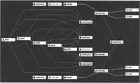
Here is a network of nodes showing something like a modified Nurbs – sphere. This would normally be thought of like 1 piece of data. For flexibility, in Maya this is how the data actually is handled and which gives you as a developer much more control. The image shows the Hypergraph which is a visualization of the Dependency Graph. The important thing about this schematic at this point is the notion and layout of nodes in general.
Everything you implement through the Maya C++ API has to be compiled before it is run. Maya embedded language (MEL) is a scripted language and therefore more suited for rapid prototyping. Make sure to appreciate the difference of making a script versus making a plug-in – and why.
So there you have some basic information on how the Maya model handles the 3d environment that you actually work in. I hope therefore it will come as no surprise when I start to delve into C++ Maya API implementations without too much warning, although I will give notice as I do so. Going through the plug-in structure combining the following in parallel seems like the only really comprehensive way of describing my way to what is finally my goal : The construction, through “artificial growth”, of an architectural structure.
– C++ source code
– Programming through the API
– Implementation in Maya
– Plugin – in behavior
Sure, you have the L-system inference problem wherein you cannot know the outcome of your evolutions, but I really don’t see that as a problem because in Architecture you have such a strict system of manual censorship and critique. And by all means, in the case of a prototype that censorship would be absolutely necessary. Still the benefits for creative aspects of such evolution seem incredible to say the least.
SO……
Earlier in this posting I talked about starting with the transformation and translation matrices – That means those matrices that rotate and rotate elements. I am now expanding this to include the direct source files who trigger these. By expanding like that I move one set of peripherals into main focus, and get another set of peripherals so that I can start to form a perspective.
It seems there are two classes who handle the matrix operations in Autodesk Maya.
– MGlobal
It provides methods for selection, viewing and manipulation of the modelling(3d graphical database) + MEL commands. There are multiple methods provided here for executing MEL commands from the API. Also includes methods for controlling error logging from the API.
– Mvector
This class provides access to Maya’s internal vector math library allowing vectors to be handled easily, and in a manner compatible with Maya data structures.
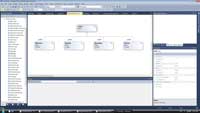
Now it is easy to use the UML diagrams created in Visual studio to branch out, and we see that
PolygonSurface.cpp and NurbsSurface.cpp make use of mvector. There are no big surprises there and that’s the way it should be, everything stacking up in a logical virtual hierarchy. That doesn’t mean this is not a necessary process though. Without these schematics it would be impossible for most people to decipher the source code is my guess.
So to use true and trusted methods I will go ahead with the method of divide and conquer. This means that the way forward can be seen as splitting the plug-in up into different functional pieces, testing them for output and mechanisms of design, and evaluating from there on. At the same time what is interesting here is how c++ classes translate into Maya classes through the API.
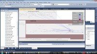
The files mentioned above have been picked for a reason, but I would also like to find the classes and functions that actually operate on the axiom(Genome – the seed of the generated structure), seen in the broad context that these actually use the axiom as input to develop geometric surfaces in Autodesk Maya. As you can see below we can start singling out groups of classes easily through the UML diagrams:

– Field – Base class for the classes describing outside forces working on the structure.
Within it we have:
.Gravity
.Attractor
.Boundary
.Vertex
But with just knowledge of C++ language syntax most people would get stuck in an endless interpretation of single – file code. So we move on to what we promised last time( Blog B3) which was the function call hierachy in Microsoft Visual Studio, and also examining MEL output from the plug-in functions.
This means that we can start to see the big picture, as we can now know the functionality that binds the source files and the classes together. Some may argue that this is starting to look like analysis paralysis, but I am absolutely aware of this, and it is absolutely necessary to go through these steps.
Just a side note on C++ application development:
Since we are talking about redeveloping a present C++ program here, I am not starting by using CRC cards or similar as you maybe would in the creative process of designing from scratch. Neither do I have to construct my own UML diagrams as such, because I can generate them from existing code. The value in using this kind of generated UML material can to a great extent already be found in just accessing dependency – and class -diagrams produced from the base model of the plug-in source code.
Commencing with the call hierarchies, there are 3 cases which I personally am interested in as a start:
The classes that we have identified through the headers and implementation files through the recent posts.
– From the project files these are:
PolygonSurface.cpp(PolygonSurface.h), NurbsSurface.cpp(NurbsSurface.h),cmd.cpp(vector.h, world.h, melutilities.h, sentence.h, word.h, nonTerminal.h ), and Scaffold.cpp(sentence.h, word.h, edge.h, predecessor.h , successor.h, axiom.h, rewriterule.h, bnf.h, melutilities.h, world.h, scaffold.h).
– From the C/C++ Standard Library;
math.h ( I want to see how certain calculations are being done)
– From the maya/include – library;
Mobject, Mstring, MvectorArray, MfnMesh, Mpoint, MfnNurbsSurface, MintArray, Mselectionmask , MstringArray , Mglobal and Mvector.
– cmd.cpp issues commands in Autodesk Maya, and as is the virtual function a lens through which to view applications in C++, the cmd.cpp is the file through which to gain knowledge of implementation in Maya through MEL(Maya Embedded language). Both through attaching the visual studio application to the Autodesk environment and the Genr8 plugin in it, and through running sequences of functions through the API and to see results in MEL – In these ways I can really start to see what is going on.
– Which brings us to Virtual functions. Just by looking at the earlier diagrams we can see how they dictate the graphed structure of the application. Nevertheless, we can not blindly believe pure inheritance is been followed, and indeed composition is also used. This we will see clearer through the sequence diagrams.
– According to the environment factors of the plug-in we can see that a lot of files are somewhat decoupled from the growth of the L-System itself, but we will have to see how they interact. Force.cpp (force.h) hold base class declarations and definitions for functionality that makes the system context-sensitive in terms of L-systems. You can start to see a complex relationship as you consider that that the Field class as displayed above is parent class for all classes that use some kind of force acting on the system, while at the same time the force class keeps track of it.
I have settled on a way to decipher certain functionality by rewriting and recompiling the plug-in, through Microsoft Visual Studio 2012, for Autodesk Maya version 2013. I will go through writing the cmd.cpp – file first, the file that issues MEL scripting commands in Maya and through which all functionality can be traced, both to – and from. I will then use the “function call hierarchy” in visual studio on the old source code for seeing the full extent of what is happening where and when, and produce examples and tests along the way in the C – posts of this blog. This is for the purpose of visualizing.

